
Course: System Design I Cubesat Project
In this course, one of the projects that grad. students work on during the semester, is the cubesat project.
The goal is to assemble a simple cubesat and be able to test the designed controller for this system. The controller is only programmed to perform around the z axis of the cubesat ( only the yaw angle is controlled ).
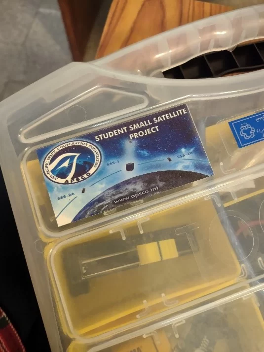
Here’s the package that the students need to assemble and test their cubesat:
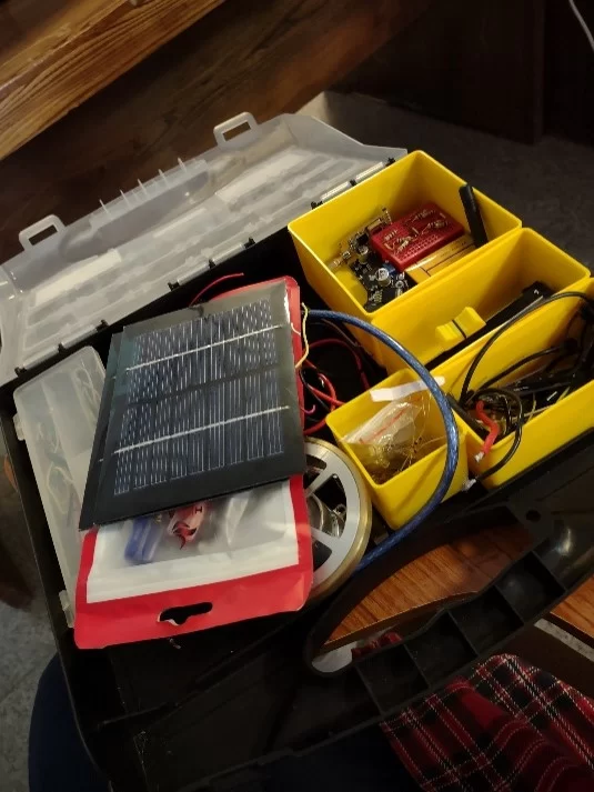
And here’s the package that has all the parts needed to achieve the required goal:
To reach this goal , the students must complete a series of activities in order to get familiar with each part’s Function and the way each part interacts with other parts of the cubesat.
These activities are:
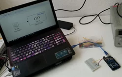
1- Arduino:
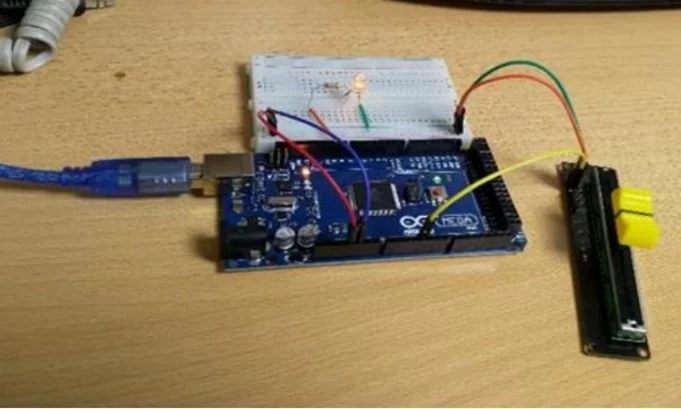
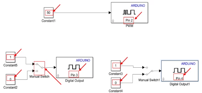
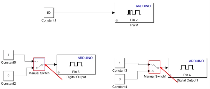
in order to know Arduio’s function in the cubesat , the students must know how to use and program the Arduino. For this , there are 2 activities designed. First one is to teach the students how to simply program an Arduino in order to turn on a LED and then making the LED blink.
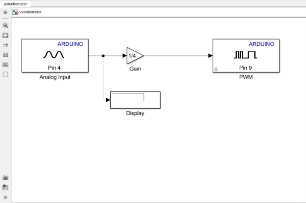
next activity is how to use an Arduino to increase or decrease an Arduino’s brightness.
2- Motor & driver implementation:
There are 2 activities designed to teach the students how to use the DC Motor and adjust the motor’s speed. First one is to simply turn on the DC motor and make the wheel start rotating both CW & CCW.
And in the next one the students learn how to control the speed of DC Motor.

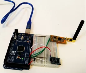
3- Sensor & communication module:
There are 2 activities designed to teach the students the function of a sensor in the cubesat. (here we are using a 9-axis gyroscope)
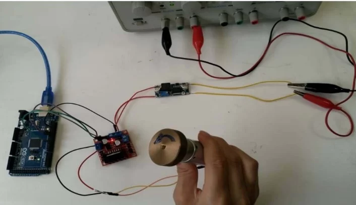
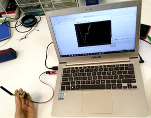
In the first one the students learn how to simply test a sensor to both make sure that it works properly and also see the changes in attitude as we move the sensor.
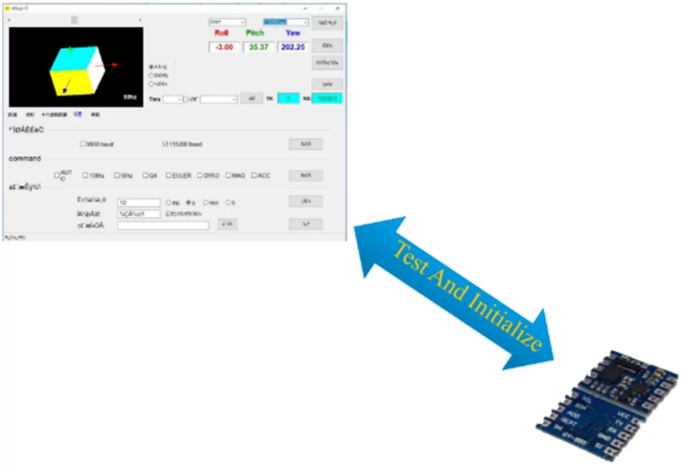
And in the next one they learn how to see test the sensor using the Wi-Fi module and the prepared Simulink simulation to see if the communication module works properly.
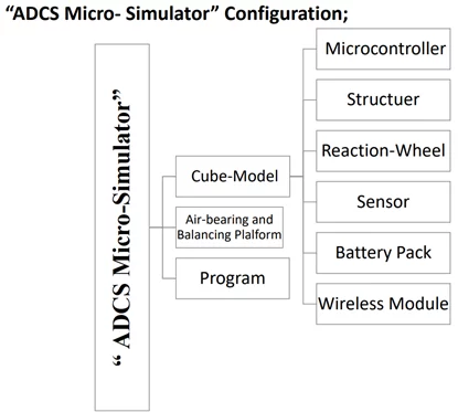
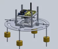
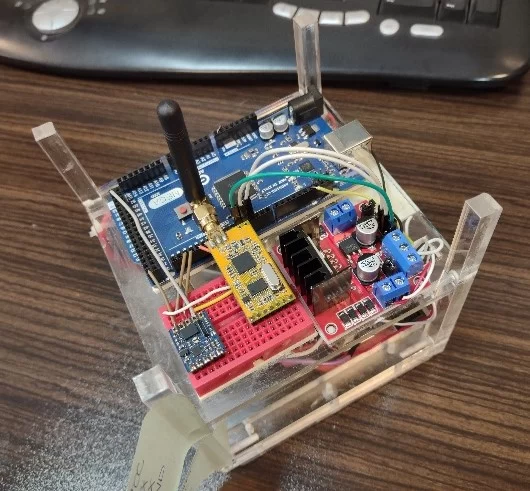
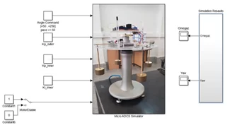
4- Micro ADCS simulator:
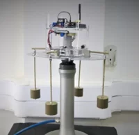
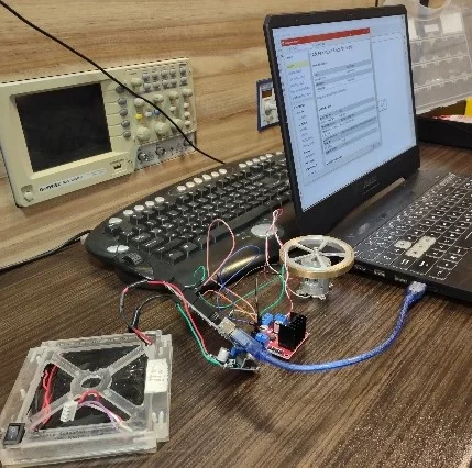
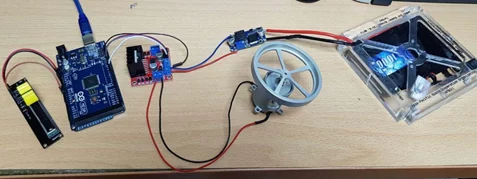
In this activity which is the last activity , the students assemble the cubesat and test the prepared controller on the cubesat.
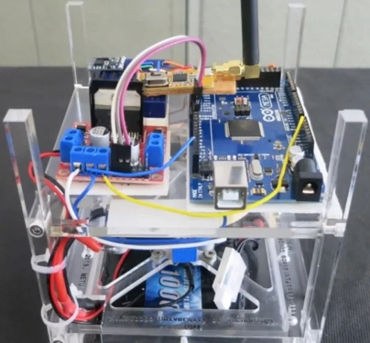
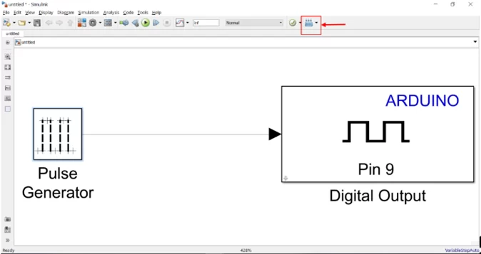
After that , the students program the Arduino using Simulink.
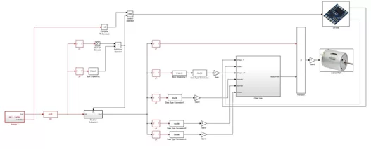
And finally they can run the main simulation to see if the cubesat is controlled properly over the airbearing.
Here’s the results of a successful test:
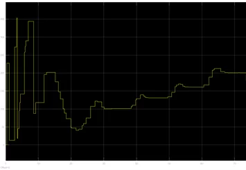
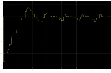
The first figure is for the yaw angle and the second one is for the wheel’s speed.
As you can see after maintaining stability around the z-axis , the controller successfully followed our desired yaw angles that were : 100 , 130 , 160 and 200 degrees.
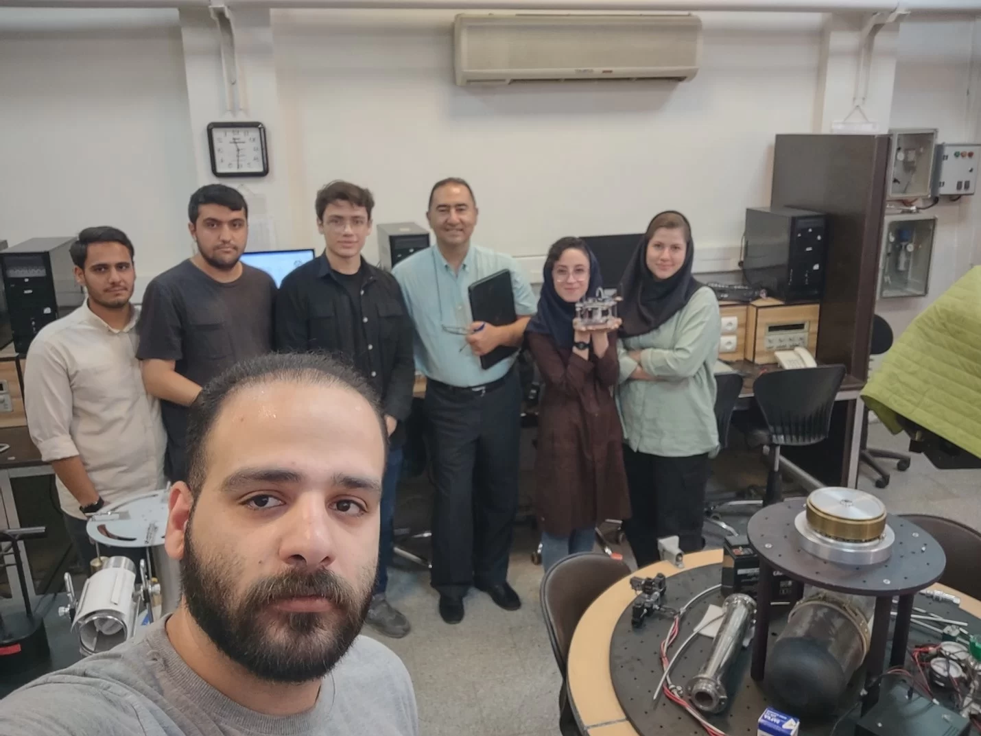
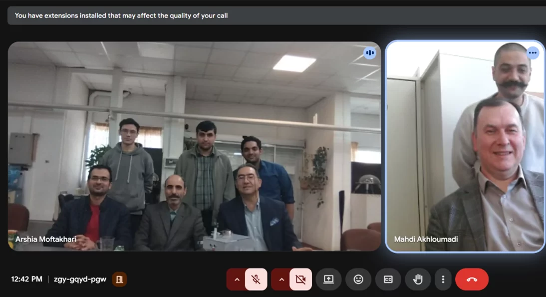
Here’s a picture of the two teams that were involved to reach this goal:

From left, in the front is Ali Moradi the TA in this course, then Reza SeratJoo, Arshia Moftakhari, Moein NazarAbadian, Dr. Mirshams (Professor of Spacecraft System Design course and the Head of Space Research Laboratory), Maryam HomayounNezhad and Niloofar Parvaneh.

Comments